T400/T500 Quad Mod Guide
This guide will detail how to modify a librebooted Thinkpad T400/T500 to use a quad core CPU. This modification takes advantage of the fact that Intel’s core 2 Duos for classic Thinkpads use the same shape of socket (G) as the more powerful quad core chips. Just the fact that the chip fits does not mean however, that it will work. The actual pins themselves have to line up to send the correct information through the corresponding connection. Since the pin layout is different for the duos and the quads, the cpu will not understand the inputs from the components on the motherboard. Thankfully, a helpful German engineer detailed his success modifying the quads to work in a T500. The original german forum post was then translated into English and posted on Tripcode’s website. Both sources note that the process could theoretically apply to the T400. I tested the mod on a T400 and found that the mod does, in fact, work exactly the same.
The resources noted above form the source material for this guide and are excellent in their own right. As usual, this guide is an extension of the source material aimed at helping people with no background knowledge.
Tools
You’ll need a few tools to get the job done. You don’t absolutely have to have a magnification device, but it really helps. All links are included as reference only, I do not endorse any of the specific products.
| Item | Note |
|---|---|
| Wire | The wire you use should be 30 AWG You also want it to be solid core. Amazon |
| Solder Wire | It should be flux (rosin) core and contain lead. Do not use lead-free Amazon |
| Soldering Iron | A cheap set is all you need. The one linked comes with its own sponge. Amazon |
| Magnification Tool | You can go with a cheap microscope or a simple magnifying glass holder Microscope Magnifying glass |
CPU Options
You have three separate options for quad-core chips listed in the table below. You’ll notice that the Q9000 is an absolute steal of a deal (especially if you’re willing to wait for shipping).
| Chip | Clock Speed | Price (USD) |
|---|---|---|
| Core Extreme QX9300 | 2.53 GHz | 80 |
| Core 2 Quad Q9100 | 2.26 GHz | 70 |
| Core 2 Quad Q9000 | 2.00 GHz | 35 |
The 2GHz clock speed of the Q9000 means that it will actually have worse single core performance than a T9800 duo (which is the best chip you can get stock). All of these chips have a 45W TDP (stock chips are 35W) which means they will all use more battery regardless of how much you push the chip.
A lot of noise is made about thermals for obvious reasons. When you change a core part of any machine, you should be darn sure that it’s not something that can kill your machine. In this case however, I think the thermal issues are over-hyped. The Linux Kernel has a decent scheduler, and you’re really not at risk of frying your machine with the QX9300. I use my T400 with a QX9300 as my daily driver and I’ve never seen it push past 70 degrees. For reference, the max temperature is 99 degrees. (you should absolutely not push it that far though). You should do the cooling mod anyway, if for no other reason than it makes your machine look cool.
Tear-down
The first step to doing the mod is to completely disassemble the machine to reveal the motherboard.
I have a T400 libreboot guide which has excellent tear-down diagrams and screw-guides. For the T500, you can refer to the libreboot docs while my T500 guide is under construction.
Modifying the Chip
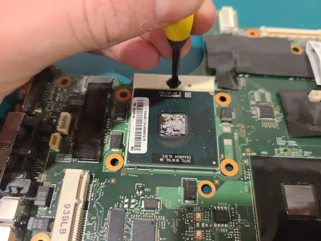
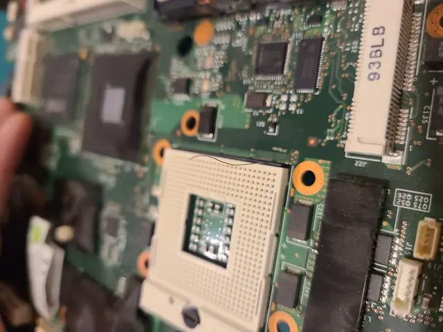
Step 1: Start by removing the existing chip from the socket. Once you make a single half-turn on the screw the chip will pop right out.

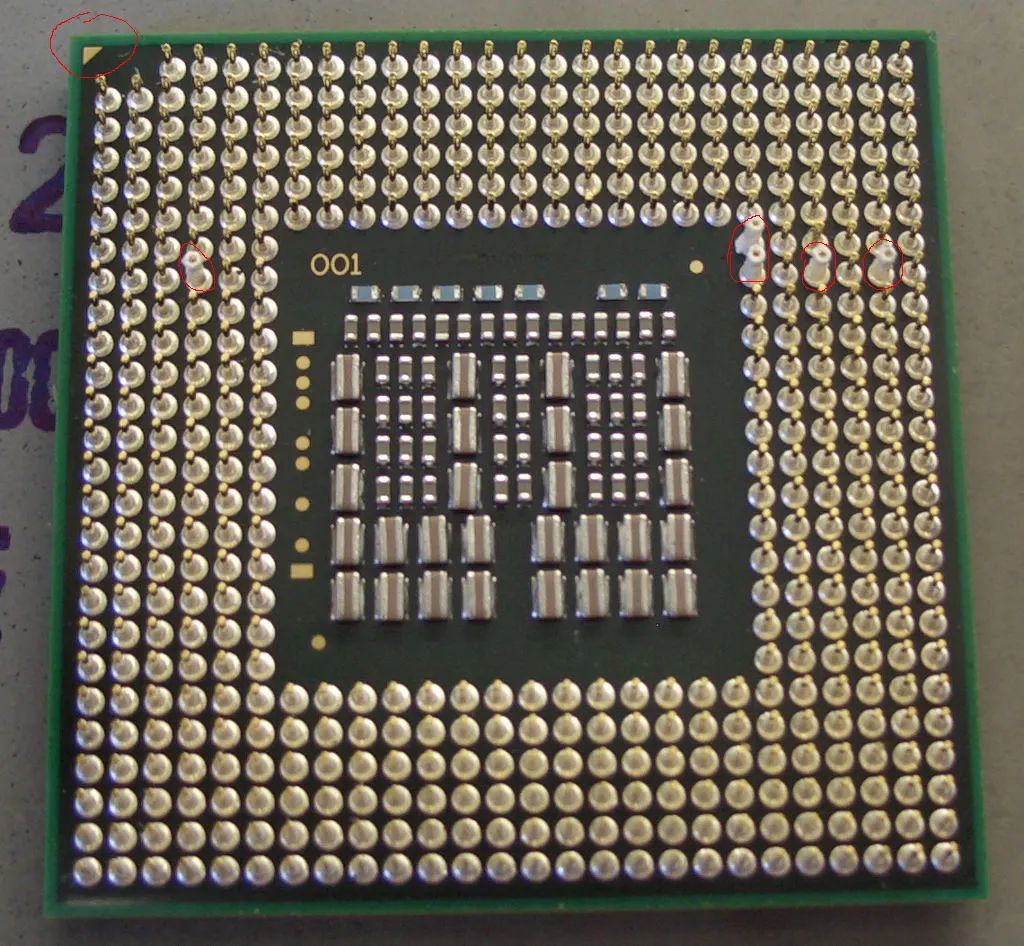
Step 2: Clip off the unnecessary pins from your quad chip. This is the trickiest part of the process besides soldering. Use tweezers to bend the pins back and forth until they break off of the quad chip cleanly. You do not need to bend the pins all the way over. By moving the pins with minimal force in all directions a half-dozen times you can break it off without bending your other pins too much. The picture below is from the original German forum post and it shows you which pins you need to break off.

When you’re done, check for any bent pins and try to bend them back into place. If a pin is just a bit out of place then it will still seat in the socket in the end. Don’t fret if your chip doesn’t go in right away, you can safely fiddle it in by hand (wiggle it on the socket until it seats). Don’t put the new chip in just yet though.
Setting up the Mainboard
Step 1: Prepare the motherboard by wiping it down with isopropyl alcohol and scrub it with a toothbrush. Make sure the area where you’ll be soldering looks squeaky clean.
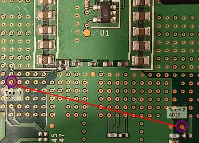
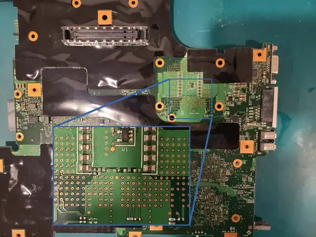
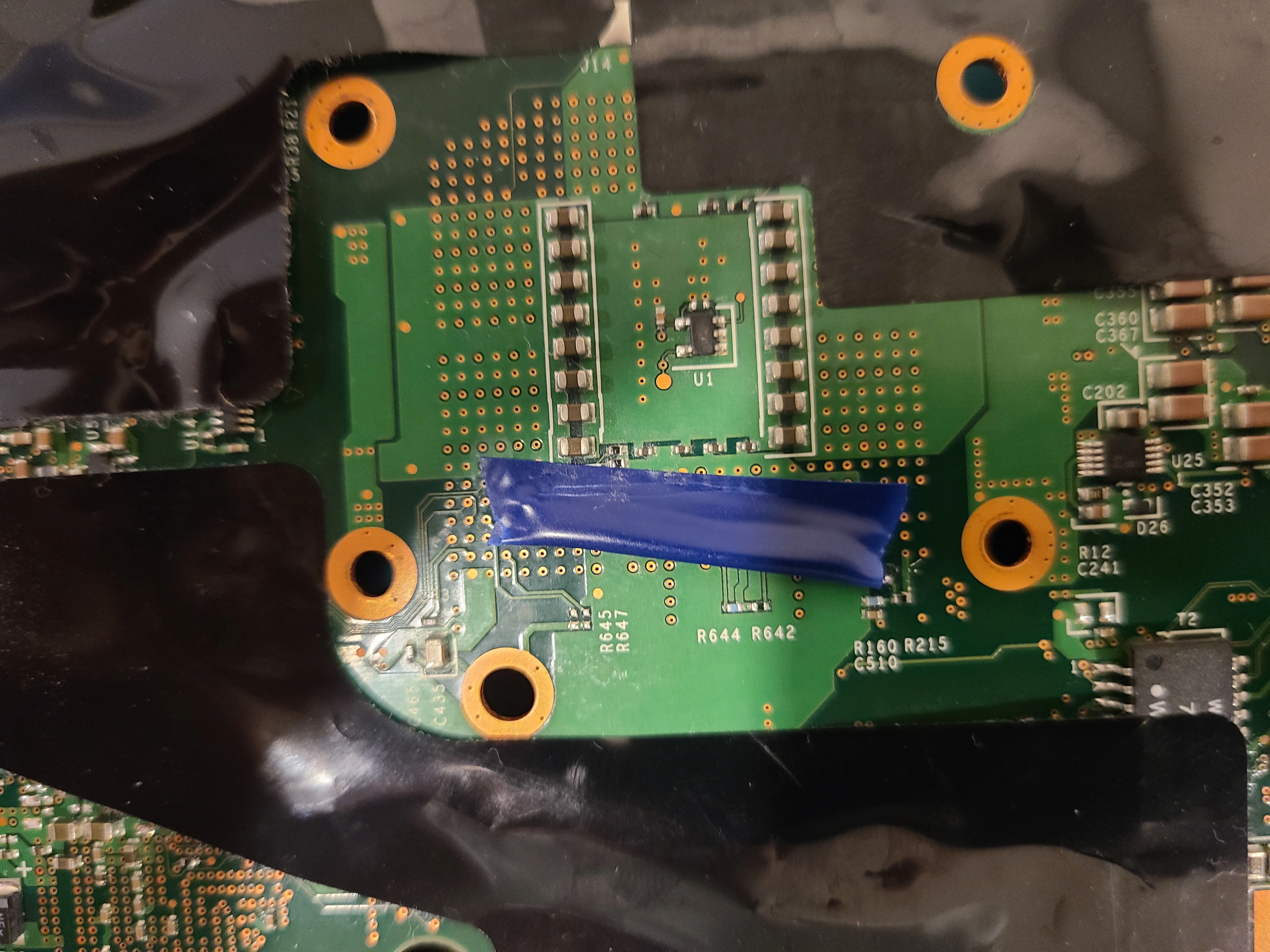
Step 2: Locate the pins to jump on the bottom of the mainboard. The image below shows where the wire should go - from pin D22 to AD26.
  |
  |
Step 3: Cut and strip your wire to make sure it fits. You want the wire to be as short as possible, and go as deep as possible into the pin holes. Making the wire the right depth is a breeze with the T400, since it goes right through the pcb on the AD26 pin.

For the T500 you’ll have to work on both ends to get the wire to the right length.
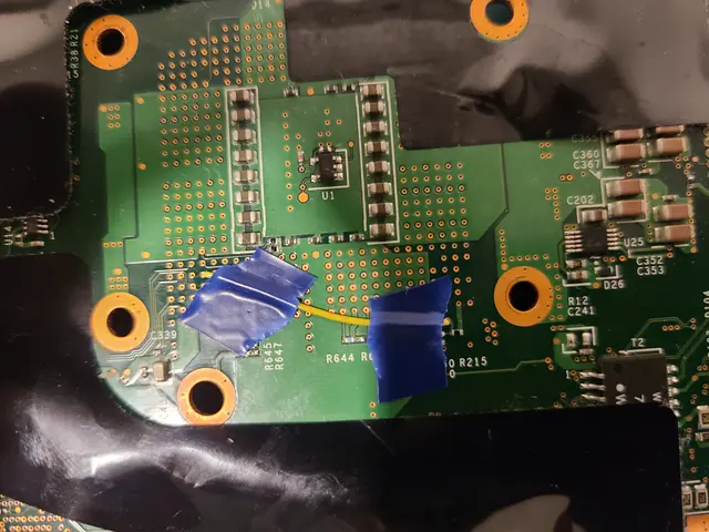
Step 4: Once you get the wire in place, you can tape it down to hold it in place while you solder it
Soldering
This is absolutely the main area of hesitancy for beginners as it seems really daunting if you’ve never soldered anything before. The basics of soldering are fortunately simple.
Soldering is an attempt to heat up two conductive materials to the point where solder will melt onto both materials to create a conductive bond. I’ll list some dos and donts to help you out if you’re still lost.
Do:
- Tin the iron by applying some solder directly to the tip of the iron as soon as it gets hot
- Hold the iron against the wire and push the solder against the opposite side of the wire
- Clean any excess solder off the pcb immediately by melting it onto the iron and wiping your iron on a wet sponge
Don’t:
- Drop steaming-hot solder directly onto the board
- You want the wire to heat up and bond with the solder, not just to be covered in solder
- Keep trying when you’re making a mess of the board with
burnt-looking material
- Once you see grime building up then you’ve likely ruined your solder tip
- If you see a mess: turn off the iron, clean up the mess, clean the solder tip by scrapping it with on a wire brush or steel wool.
The legendary libreleah herself reached out to me recently about this section. Not only did she give me some invaluable pointers and even test me on my knowledge, she pointed me to some fantastic resources. The best of the resources I got from that conversation were the soldering tutorial videos from paceworldwide. There are innumerable great videos in that series; if you want the bare minimum to feel confident going into this specific solder job then watch the introduction and then component soldering.
Step 1: Locate the wire under your microscope/magnifying glass. You can make do without magnification, it’s just more difficult.

Step 2: The moment of truth. Carefully hold the tip of the soldering iron against the wire while you touch the solder to the opposite side. Once the wire is hot enough, the solder should melt into the pin hole and onto the wire.
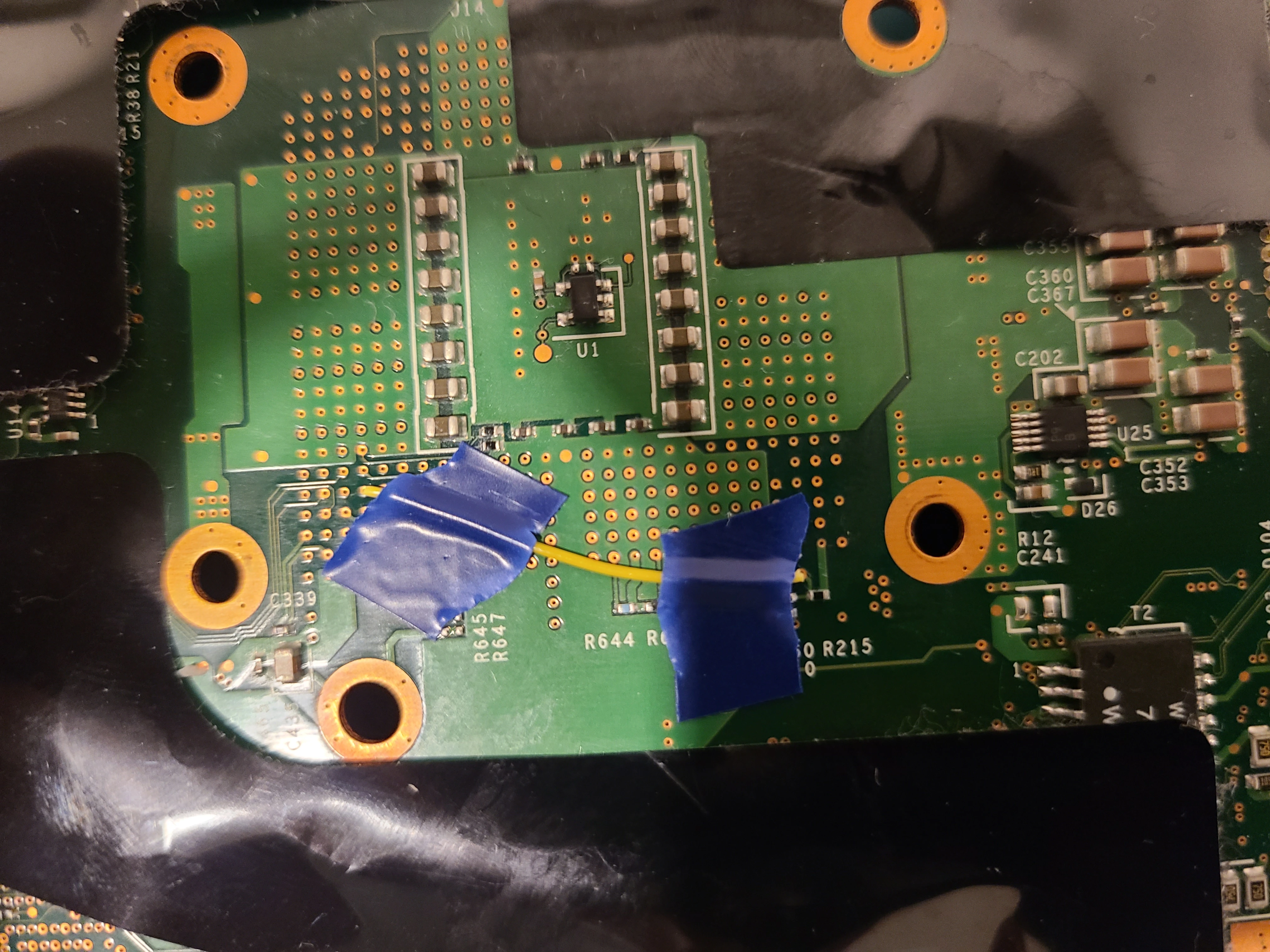
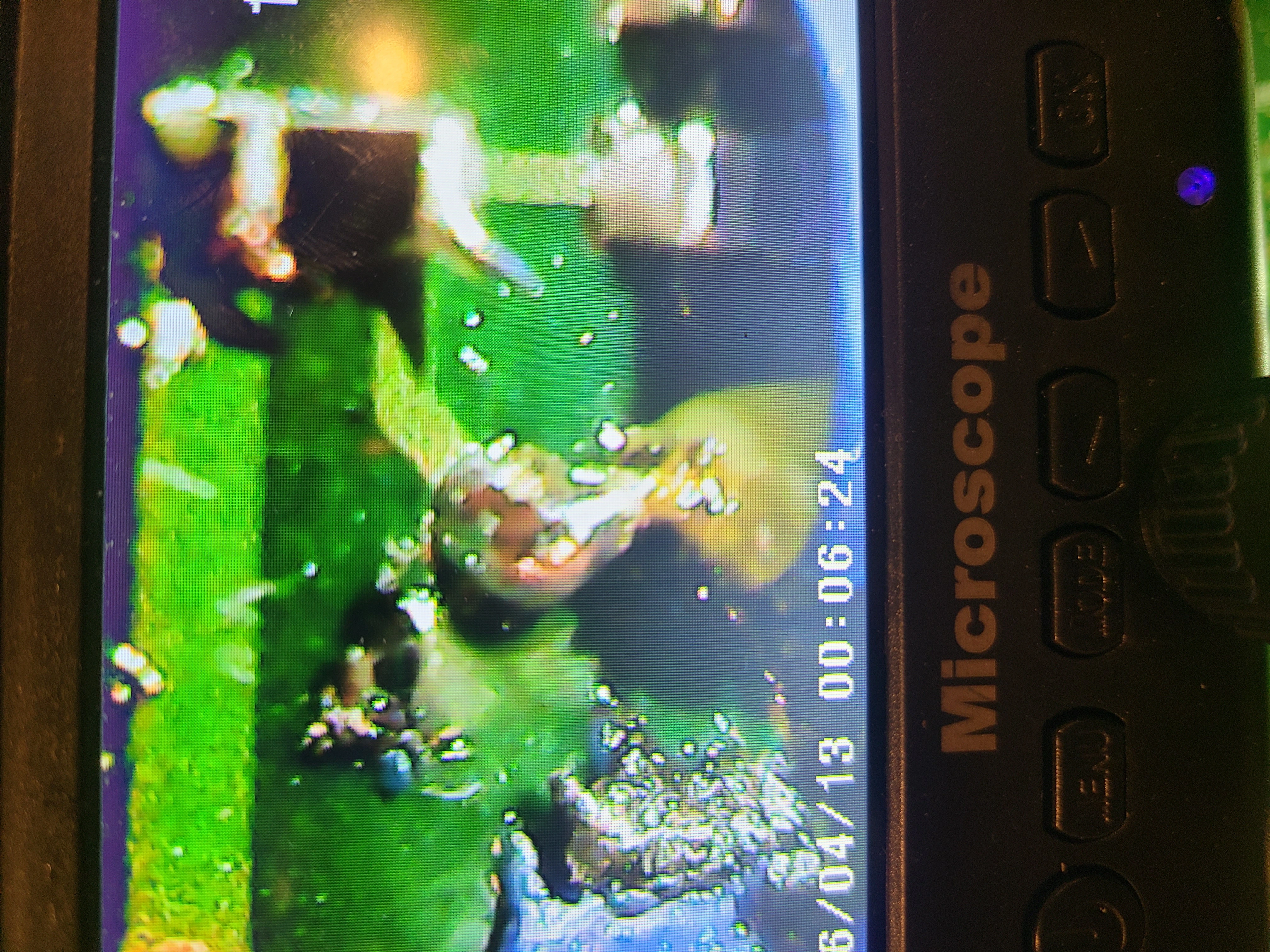
Step 3: Check that you have a good connection. The main thing to avoid is a bridged connection. A connection is bridged where solder spreads to unintentionally connect two components. In this case, you want to make sure your solder hasn’t spread to other pins. The photo here is not a very good one, I took it before cleaning the board and after using an old solder tip. Still, the image should give you a reference of how much solder you need and what it looks like on the wire.

Finishing up
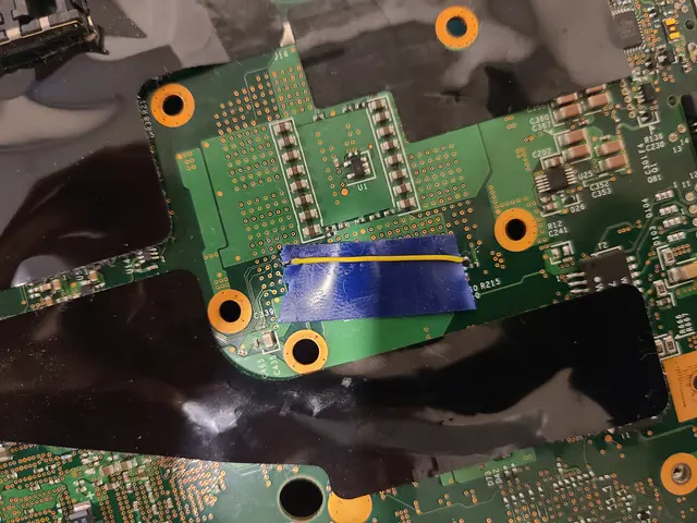
Step 1: I always place a piece of electrical tape below the wire and fold it over. I have no scientific reasons for doing this, but I haven’t had a single issue with a quad mod since I started doing it. I figure it helps because it will stop the CPU mount from crushing the wire and stop the wire from bridging if it moves during re-assembly. Simply push some tape underneath the wire, then fold it over on top of itself.
  |
  |
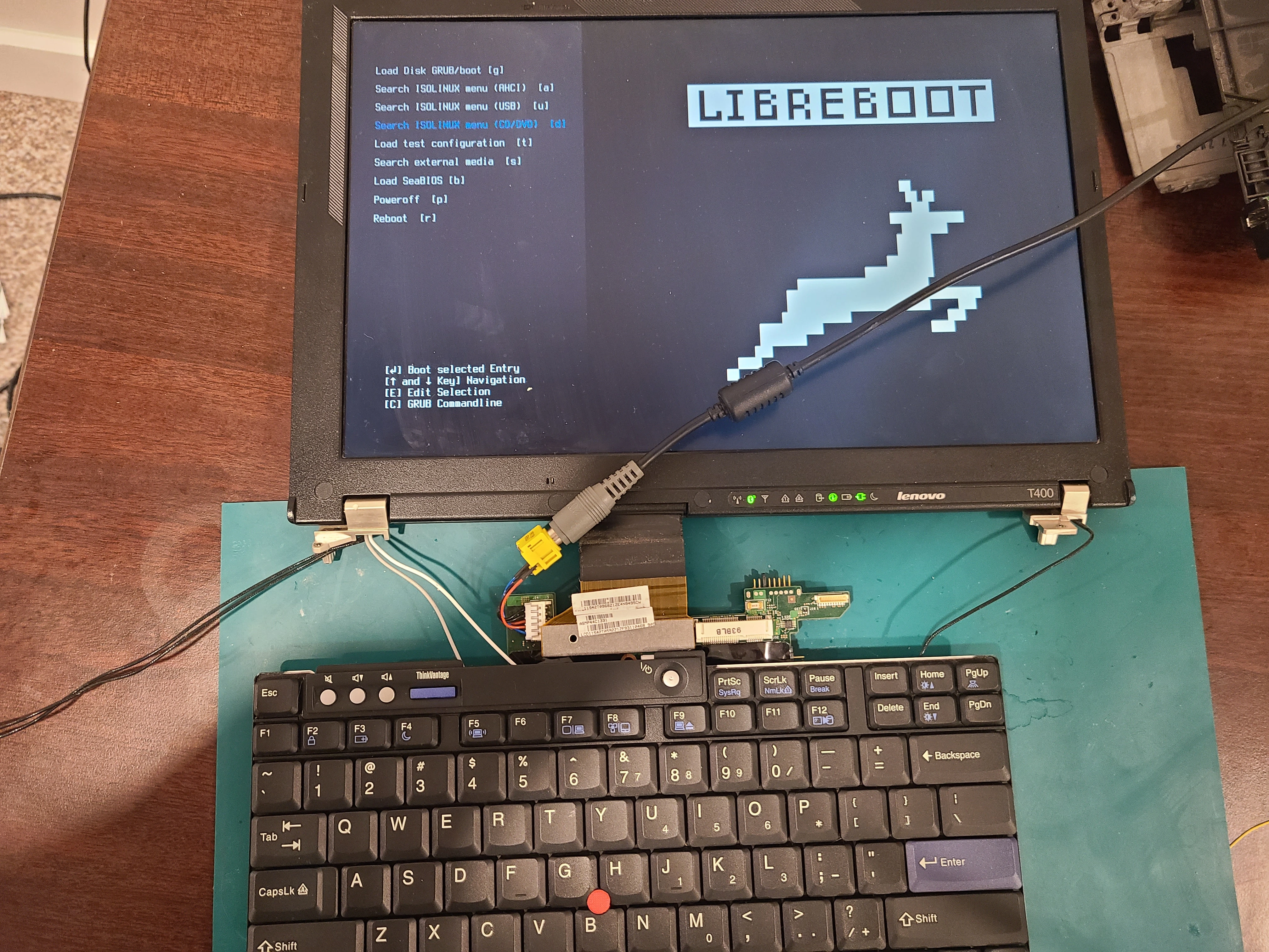
Step 2: Fire in the new CPU then plug in the display, keyboard, and power to test if everything is working. If the machine doesn’t boot, try cleaning and soldering the mainboard again.