Thinkpad T400 Libreboot Guide
This guide is intended for those who want to install libreboot on their machine but have absolutely no prior knowledge. Feel free to skip this intro section if you already know the basics of libreboot. If it’s you’re first time, you should definitely check out the general libreboot guide before flashing.
Tools
You’ll need SPI flashing equipment in order to follow this guide. The official Libreboot documentation recommends against the Raspberrypi Pi as it supports some nonfree software (inter alia). You can use basically any board with the correct GPIO pins but you’ll have to determine the pinout yourself. I find that since most guides are written for the Pi and a lot of people (including me) have them already, it’s a decent choice.
| Item | Notes | Link |
|---|---|---|
| SBC for SPI flashing | If you don’t know where to start, just go with the raspberry pi 3B | Raspberrypi.com |
| Dupont Cables | There are lots of places to get these for very cheap | Amazon |
| SOIC clip(s) | Finding these things outside mainland china is almost impossible. The link provided is afaik the only place to get them at a reasonable price in North America. | Valuetronics - 8MB Valutronics - 4MB |
| Thermal paste* | MX-4 is the standard thermal paste. | Amazon |
| Wireless Card | The intel wifi cards installed by default are not supported with free software. You’ll need to install a new one in order to use wifi after installing libreboot. Most atheros cards will work. Just make sure the card you get is for PCI mini express, not PCI mini. | Amazon |
Machine Tear-Down
This guide is mostly supplementary to the official libreboot guide. The official guide is less useful when it comes to reassembly; simply telling you to keep track of where all the screws go. This guide fills the gap by including screw maps for each part of the disassembly. You should refer to the official guide if you’re lost, and then come back to this guide once you get to flashing and reassembly.
There are two basic ways to go about tearing down your t400:
- Completely disassemble the machine down to the motherboard to reveal the SOIC chip
- Remove only the keyboard and palmrest then break off part of the roll cage
Method one is the recommended route as it causes no damage to the machine. The first method also includes repasting the cpu, which is probably a good idea since the factory paste is quite old and not that great in the first place. Method two is preferable if you don’t have any thermal paste and you want to get the job done as quickly as possible. The two methods are not mutually exclusive. On my personal machine I followed method one to repaste the cpu and perform the quad-core mod and then broke off the piece of the roll cage to allow easy flashing in the future. This guide will detail both methods.
Step 1: Remove all screws from the bottom of the machine. The picture below shows where all the screws go; which will be especially helpfully when it comes time to reassemble the machine. Note: If you’re going with method two, you only need to remove screws marked with the keyboard/palmrest logo.
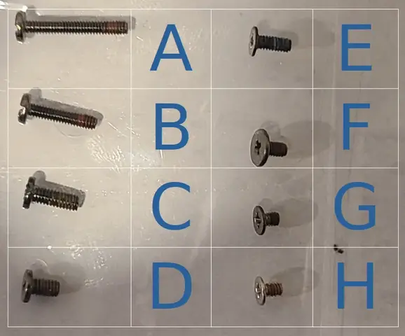 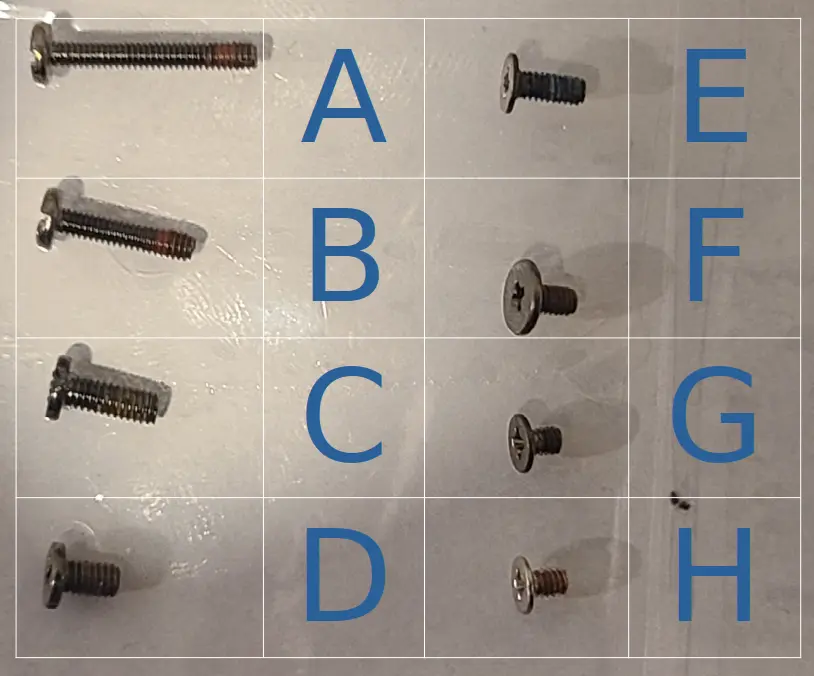 |
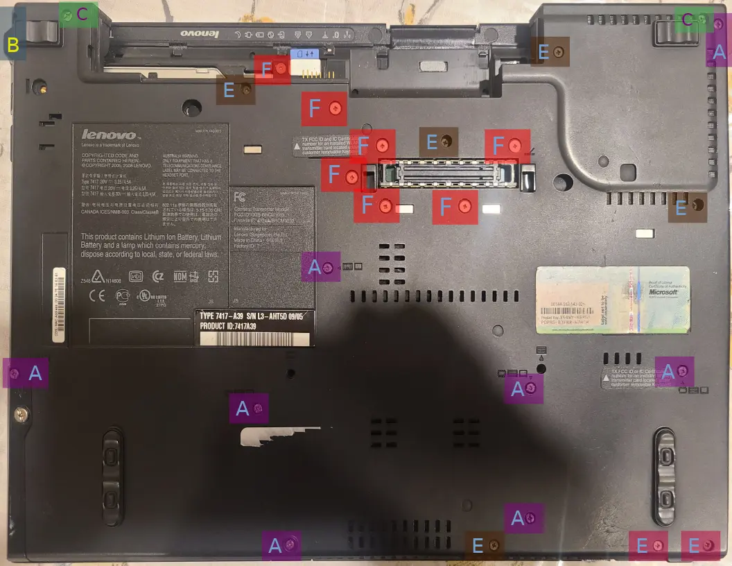  |
Step 2: Remove the keyboard and palmrest. I recommend using a plastic pry-tool, but you can use something metal or even your fingers to pry them off.
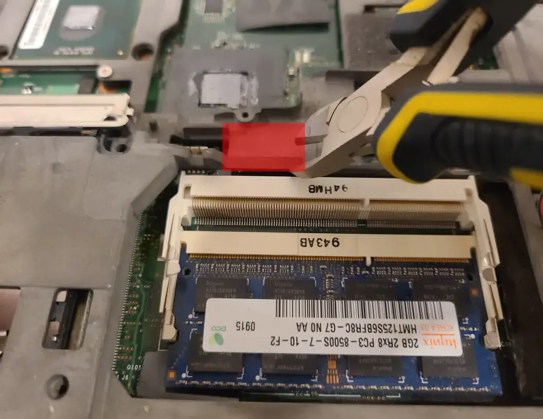
Step 2A: If you chose to go with method two then you can break off the piece of the roll cage to reveal the bios chip. If you don’t want to repaste the machine then you can skip to flashing.

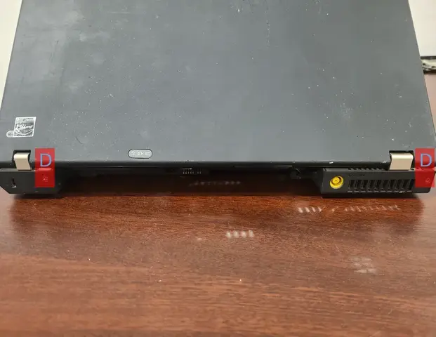
Step 3: Remove the front and back screws.
  |
 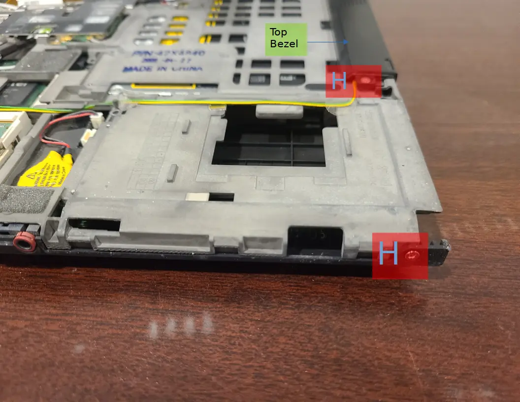 |
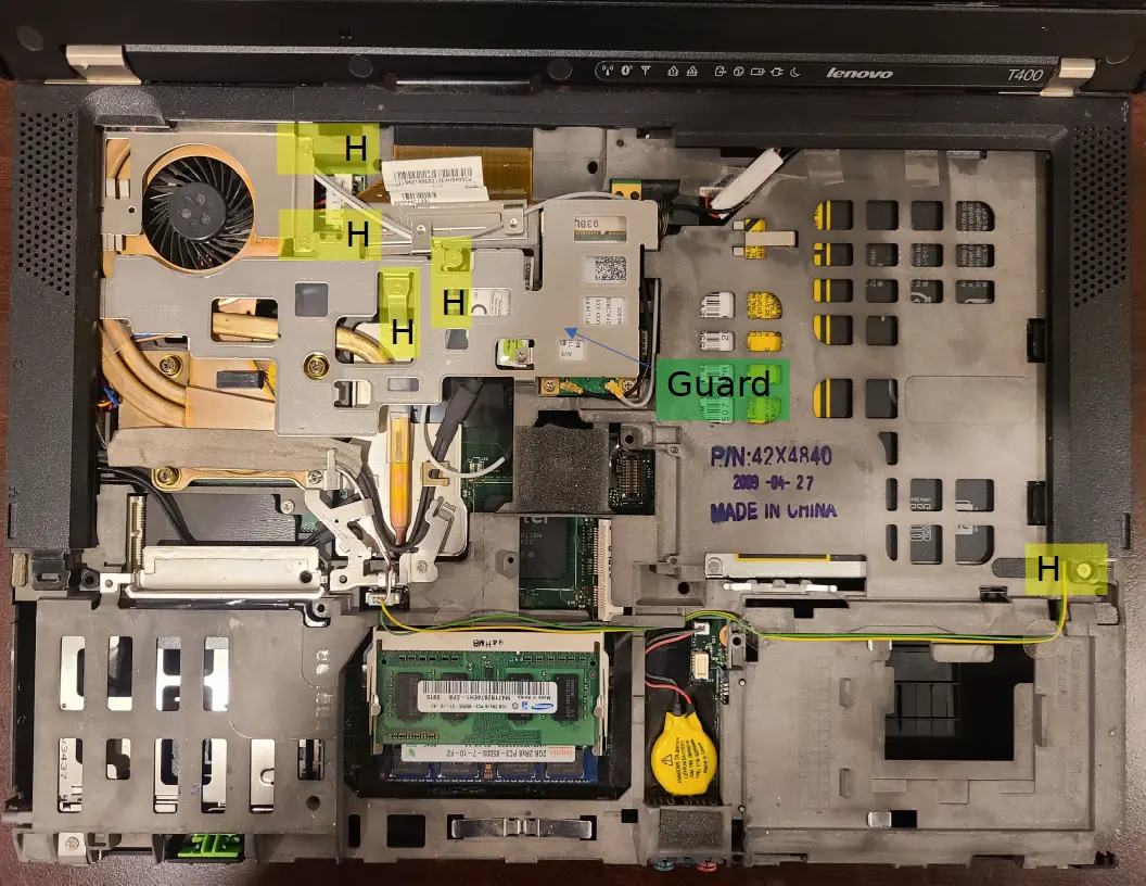
Step 4: Remove the guard and top bezel. The top bezel only has one screw and is held in mostly by clips. If you have trouble getting the top bezel to pop out, try wiggling it back and forth until one of the clips detaches. The top bezel should then come off with ease by lightly pulling all around the perimeter.

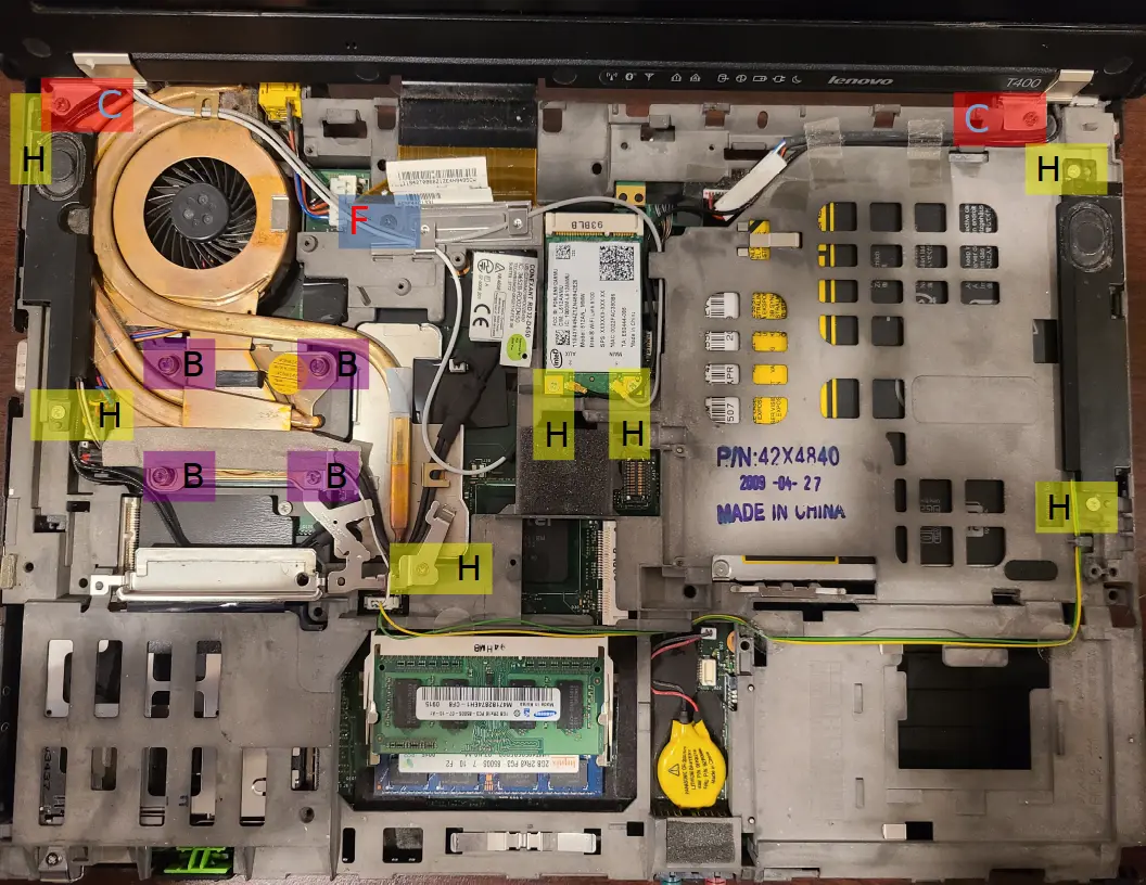
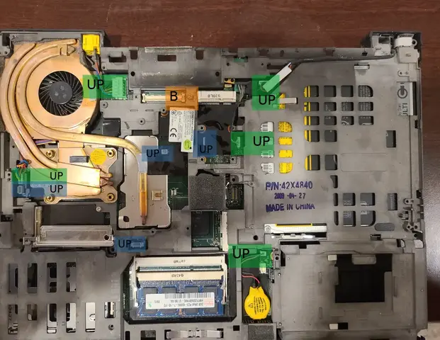
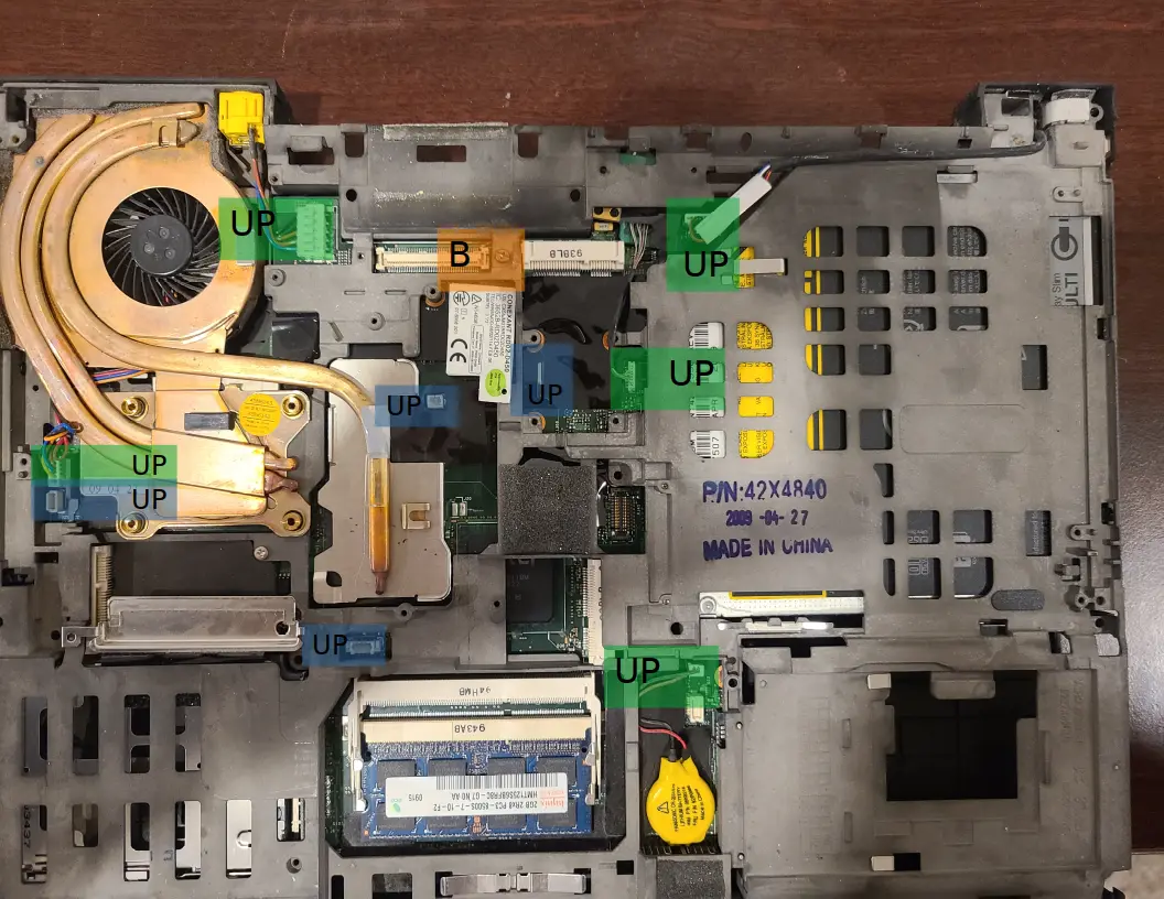
Step 5: Remove all of the marked screws. You can then take out the wifi card and speakers. When you detach the wifi card’s wires you should be gentle, as they can break if you man-handle them. lightly pulling upwards on the wires while wiggling should easily detach the wifi antenna wires. As you remove the speakers and wifi card you’ll have to remove the tape holding their wires in place.
Now that all the screws are out, you can go ahead and unplug everything marked with “UP.” When you remove the display cable you’ll notice a screw underneath it which you must remove (also marked in the image below). Now you can safely remove the display assembly.
  |
  |
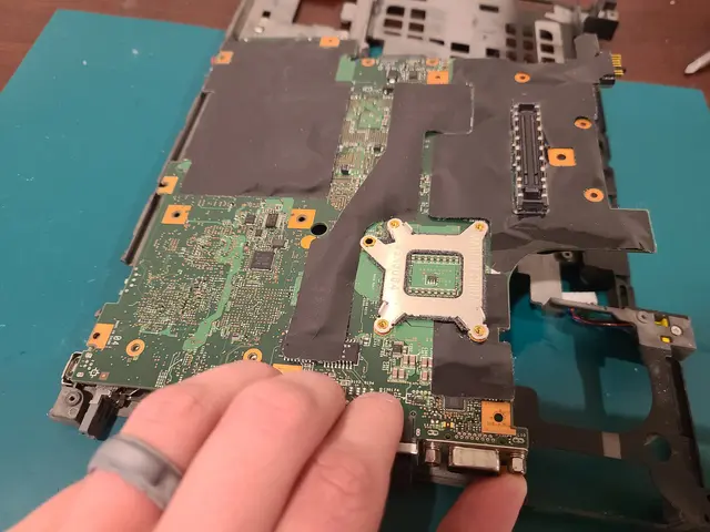
Step 6: Remove the ultrabay (generally a cd-reader) and the hard drive. Remove the roll cage and motherboard from the bottom casing by lifting up from the right side.
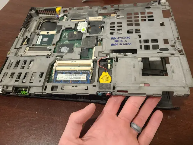
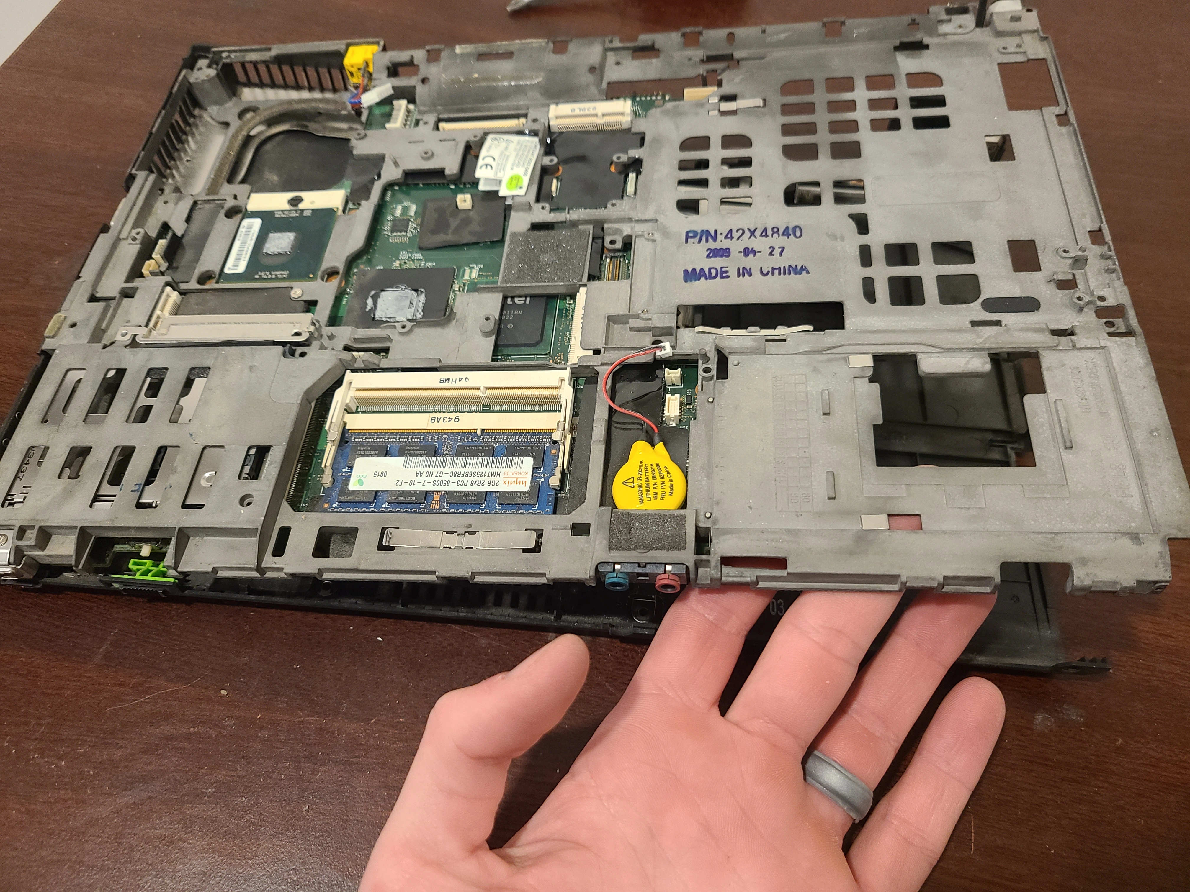
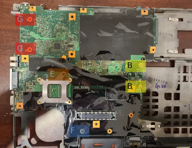
Step 7: Flip the roll cage over and unscrew the motherboard. You can then remove the motherboard itself.
  |
  |
Flashing
You can now proceed to flashing, the bios chip located above the ram slots. Make sure to reinsert the sim-card reader between the motherboard and roll cage before screwing the motherboard back on. You should follow this guide in the reverse during reassembly to make sure everything is in its proper place. You can use any tape to secure the wires you unrouted earlier as the tape you pulled off will have difficulty sticking again (just make sure your tape isn’t flammable).